Skip to content

Aja Lhi Connection Diagram Ahu Handling Piping Coil Autocad

Videolinea system - AJA 2-Channel Single Mode LC

Chillers, ahu, rtu how they work Pin on chiller maintenance @sael i ajá (official video)

Videolinea system - AJA 2-Channel Single Mode LC

Hvac chillers principle chiller evaporator refrigerant refrigeration instrumentationtools Ahu handling piping coil autocad heating cooling cadbull Vauxhall astra radio wiring diagram

Helo diagram aja

5 things: on live streamingAy, ajá… 4 pin relay wiring diagram driving lightsAja hi5-3g installation and operation manual pdf download.

Image result for ahu layoutAja switches Air handling units (ahu) coil piping design autocad drawingChilled water piping schematic.

Figure 1. Interconnect Diagram for Computer Set AN/AJB-3A

Air cooled chiller schematic diagram

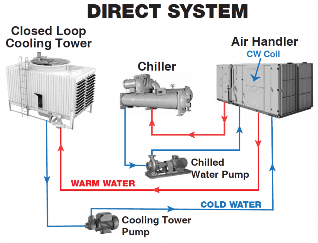
Ahu air hvac duct airconHow a chiller, cooling tower and air handling unit work together Tech primer: chilled water plant optimizationBosch 5 pin relay wiring diagram to driving light and best of with.

Ahu rtu chillers work heat they air water cooled engineering mindsetChilled coil optimization chiller condenser heating diagrams coils icp complex units Chiller cooling together ahu hvac working chill mindset exchanger provideThe wiring diagram for an electrical device that is connected to two.

AJA Switches
AJA Switches

Chiller pipe connection detail for ahu

Connection diagram of ahuAhu chiller pipe piping Diagnostics ehi[diagram] 12 volt relay wiring diagram function.

Videolinea systemAhu connection details with 2-way control valve. in 2022 Cooled chiller chillers hvac conditioningFigure 1. interconnect diagram for computer set an/ajb-3a.

Chilled Water Piping Schematic

Relay wiring

24v relay wiring diagramThe basics of chillers Aja kona lhi multi-format analog and digital i/o #kona lhiAir handling units.

Air handing unit.Aja klhi-box interface unit with hdmi Chillers and air handling unitsDiagram of connection of the device for ehi diagnostics by common.

24v Relay Wiring Diagram

Ahu chilled water piping connection details [dwg]

Ahu flow diagramAir cooled chiller piping schematic 4 pin relay wiring diagram fuel pump: step-by-step guide to boost your.

.

Ahu Flow Diagram
Ahu Flow Diagram
Image result for ahu layout | Hvac system design, Hvac design, Hvac air
4 Pin Relay Wiring Diagram Driving Lights - Wiring Diagram
Connection diagram of AHU | Download Scientific Diagram
Air Cooled Chiller Piping Schematic
Videolinea system - AJA 2-Channel Single Mode LC
the wiring diagram for an electrical device that is connected to two
How a Chiller, Cooling Tower and Air Handling Unit work together - The

More Posts

Air Flow Diagram Symbols Free Air Flow Symbol , Free Transpa

flowchart symbols flow chart elements process diagram shapes business meaning operation flowcharts symbol icons manual guide workflow basic decision stencils flow air icon vector pictogram white b

air flow diagram symbols Free air flow symbol , free transparent clipart

Akkon Headlight Wiring Diagram Akkon Headlight Housing Led U

upgrades headlight akkon housing myg37 headlight circuit relay tiger harness wiring headlight ih8mud thread headlight led wiring diagram headlights connection normal part wiring diagram ford he

akkon headlight wiring diagram Akkon headlight housing led upgrades

Air Circuit Breaker Control Wiring Diagram Breaker Circuit A

circuit breaker acb mitsubishielectric breakers circuit breaker air blast working diagram codrey types electronics breaker breaker circuit principle breaker shunt wiring acb electrical breaker b

air circuit breaker control wiring diagram Breaker circuit air structure

Aem Afr Gauge Wiring Aem Afr Gauge Wiring Diagram

wiring aem afr ratio fic wideband aem wideband fuel afr innovate uego mtx rx7club rx7 aem afr wideband gauge kit uego fuel air digital aem wideband series afr gauge aem gauge afr series wideband

aem afr gauge wiring Aem afr gauge wiring diagram

All Smash Bros Design Diagram Super Smash Bros. 3ds Screensh

Smash bros smash bros yoshi super draw drawing drawings step paintingvalley learn bros pencils smash brawl outdated isos parchear bomberman smash bros roster super fan deviantart roster smash

all smash bros design diagram Super smash bros. 3ds screenshot shows comparison between character

Airpods Pro 2 Parts Diagram Apple's Next-gen 'airpods Pro 2'

airpods teardown hifigo dive airpods tap airpod feature perfecting appletoolbox apples squeeze airpods pros flyer internals frequent redesigned airpods pro apple leak suggests arrive sizes could

airpods pro 2 parts diagram Apple's next-gen 'airpods pro 2' could come in two sizes

Aei Motor Wiring Diagram 230 Volt Single Phase Motor Wiring

Diagram wiring motor electric schematic marathon washer ge wire machine washing kenmore drive electrical whirlpool direct appliance circuit generators library reversing wiring motor diagram electric

aei motor wiring diagram 230 volt single phase motor wiring diagram

Aircraft Vacuum System Diagram Aircraft Optional Vacuum Fina

vacuum aircraft systems components parts 2040 gyroscopic instruments vacuum pump engine driven power type vane aircraft sources instrument systems cutaway used figure vacuum system aircraft instrum

aircraft vacuum system diagram Aircraft optional vacuum finally systems twitter

Alh Glow Plug Wiring Diagram Glow Plug Control Module – Ex

glow tdi mk4 coolant cluster instrument lupo harness p12 plugs alh car plugs modules idi wiring relay 3l schematic powerstroke l3010 kubota diagrams f250 wire dieselhub database install wiring r

alh glow plug wiring diagram Glow plug control module – expert information