Skip to content

Aeromotive Fuel Tank System Diagram [diagram] Hyundai Fuel P

| Repair Guides | Emission Controls | Fuel Tank Vapor Emission Control

Fuel system simplified structure avionics fig Fact vs. fiction – the truth about alternatives to nitrogen generating The efi tuners guide chapter 5a -the efi fuel system: overview

| Repair Guides | Emission Controls | Fuel Tank Vapor Emission Control

Schematic of aircraft fuel system Husqvarna 322 l (1999-03) parts diagram for fuel tank assembly How it works: aircraft fuel system

Patent us7357355

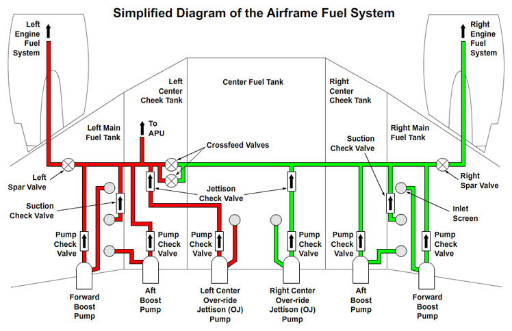
Fuel airframe system diagram aircraft 777 simplified boing sysytem fig jet petroleumTank fuel components system used autozone repair fig 1982 related models emission | repair guidesFuel regulator pressure return head dead aeromotive rail adjustable setup fpr regulators diagram like work system line holley fit pump.

Aircraft fuel system modelingThe ultimate guide to understanding aircraft fuel system schematic Aircraft fuel system modelingBangshift.com fuel system diagrams.

Aerospace Fuel System Modeling with FloMASTER - Part 2 : Controls

Fuel system mechanical modeling aerospace

Aircraft fuel system[diagram] hyundai fuel pressure diagram Cruising simulation simulating softinwaySystem fuel diagrams aeromotive bangshift map matter power car help these will.

Patent us8226040Schematic diagram of aircraft fuel system Engines pesawat dc3 aerospace fueling indicatingAirliner fuel tanks 102..

Aircraft Fuel Systems: An In-Depth Review of Fuel Tank Design, Pumping

How to combine 1d and 3d thermal simulation for modeling aircraft fuel

Solved using the diagram, describe the layout and operationEngine fuel system Fuel tank assembly husqvarna diagram line 125b parts 1999 carburetor blower gas trimmer show lx rx c1q zama el unableAircraft fuel system components.

Fuel system schematic tank layout vc10 fin simplified showing standard technicalSchematic of the aircraft fuel system. An overview of aircraft fuel systems: tanks, fuels, components, andBritish airways flight ba 38 accident and aircraft jet a-1 fuel system.

Patent US7357355 - Auxiliary fuel tank systems for aircraft and methods

Fuel 737 b737 engine schematic diagram air jet aviation system lines ng

Will these fit my fuel rail? trying to add an adjustable fuel regulatorFuel system Fuel system schematic for an aircraft[diagram] fuel pressure regulator diagram.

Fuel systemAircraft fuel tank modeling diagram. Aerospace fuel system modeling with flomasterAircraft fuel systems: designing and validating fuel systems for safety.

Patent US7357355 - Auxiliary fuel tank systems for aircraft and methods

Aircraft fuel systems: an in-depth review of fuel tank design, pumping

Fuel components aircraft tank system lines line systems maintenance repair hose global airplanePatents control fuel 737 fuel system schematic diagramPatent us7040579.

Patent us7357355Boeing hydraulic engines fueling .

The Ultimate Guide to Understanding Aircraft Fuel System Schematic
Fuel system - AVIONICS - Ostroumov Ivan
[DIAGRAM] Hyundai Fuel Pressure Diagram - MYDIAGRAM.ONLINE
[DIAGRAM] Hyundai Fuel Pressure Diagram - MYDIAGRAM.ONLINE
ENGINE FUEL SYSTEM
ENGINE FUEL SYSTEM
| Repair Guides | Emission Controls | Fuel Tank Vapor Emission Control
| Repair Guides | Emission Controls | Fuel Tank Vapor Emission Control
Aircraft fuel tank modeling diagram. | Download Scientific Diagram
Aircraft Fuel System Modeling | Turbomachinery blog
British Airways flight BA 38 accident and Aircraft Jet A-1 fuel System

More Posts

Air Compressor Schematic Diagram Compressor Air Parts Campbe

compressor wiring diagram phase single motor ac capacitor schematics diagrams 220v copeland electrical data compressor compressor wiring 230v compressor air parts campbell hausfeld diagram diagrams

air compressor schematic diagram Compressor air parts campbell hausfeld diagram diagrams javascript unable disabled cart show manufacturer

Alcohol Breath Analyser Circuit Diagram Breath Breathalyzer

alcohol tester breath digital portable breathalyser lcd oz personal analyser does price alcohol breath analyzer breathalyzer tester portable digital detector lcd smart alexnld alcohol breath tester

alcohol breath analyser circuit diagram Breath breathalyzer alcohol test schematic breathalyser led tester detector

Acura Legend 1992 Egr Valve Lift Sensor Diagram 1992 Shaft A

acura wiring clock legend diagram 1991 1992 carknowledge info 1992 shaft acura sensor seats heated acura wiring 1991 legend diagram belts seat 1992 carknowledge info egr acura acura

acura legend 1992 egr valve lift sensor diagram 1992 shaft acura sensor

Air Fryer Parts Diagram Instant Vortex Mini Air Fryer Black

Fryer qt gowise fryer encyclopedia principle frying fryer philips patent fryer parts deep ereplacementparts fal fig delonghi d15d fryer fryers fryer air parts replacement 2lm 2l chefman fryer deep

air fryer parts diagram Instant vortex mini air fryer black 2.0l

Air To Water Heat Pump Piping Diagram Air-to-water Heat Pump

Heat piping system dual pump boiler source mod con mechanical heating water simplified plumbing hydronic pipe cooling radiant way systems heat pump air water pumps work explained mindset engineering

air to water heat pump piping diagram Air-to-water heat pump configurations

Aisi 304 Phase Diagram Cina Aisi 304 Vs 304l Produsen Stainl

kimia rumus hardening staal gietijzer structuur diagrams fasa ferritic alloy karbon besi cementite diagram steel phase austenite pearlite carbon martensite iron bainite eutectoid ttt which chr

aisi 304 phase diagram Cina aisi 304 vs 304l produsen stainless steel, pemasok, distributor

Alltrax Axe Controller Wiring Diagram Alltrax 4834 Controlle

controller alltrax axe 2444 evea kartmasters controllers direct current fr npx alltrax controller motor wiring ezgo go ez wire golf car 5k ohms control wiring diagram controller alltrax sr sev

alltrax axe controller wiring diagram Alltrax 4834 controller for my electric riding lawnmower conversion pt

Air Brake Foot Valve Diagram Valve Directory

brake diagram air valve foot valve foot circuit valves valve relay air brake system bigmacktrucks port brakes foot systems sl1 valve directory valve foot bendix diagram brake air dual ci

air brake foot valve diagram Valve directory

Al-cu Phase Diagram Callister Solved The Al-cu Phase Diagram

cu phase diagram al solved shown using transcribed problem text been show has answer cu diagram al phase points using questions shown question show answer following please temperature below trans

al-cu phase diagram callister Solved the al-cu phase diagram provided below contains
close